Insights and Commentaries
Site characterisation for storage in the near shore Gippsland Basin
15th September 2015
Topic(s): Carbon capture, CO2 storage, Engineering and project delivery, use and storage (CCUS)
CarbonNet is investigating the potential of geological formations in south eastern Australia to store significant volumes of carbon dioxide and form the basis of a multi-user carbon capture and storage (CCS) network. Earlier this year the Global CCS Institute published two reports from CarbonNet, one a summary and historical background to the project and the other describing the development of a commercial framework. A new report released by the Institute details the geological site characterisation work undertaken by CarbonNet. In this Insight the Institute's Senior Adviser for Storage (Asia Pacific), Chris Consoli introduces the report and discusses some of the key findings.
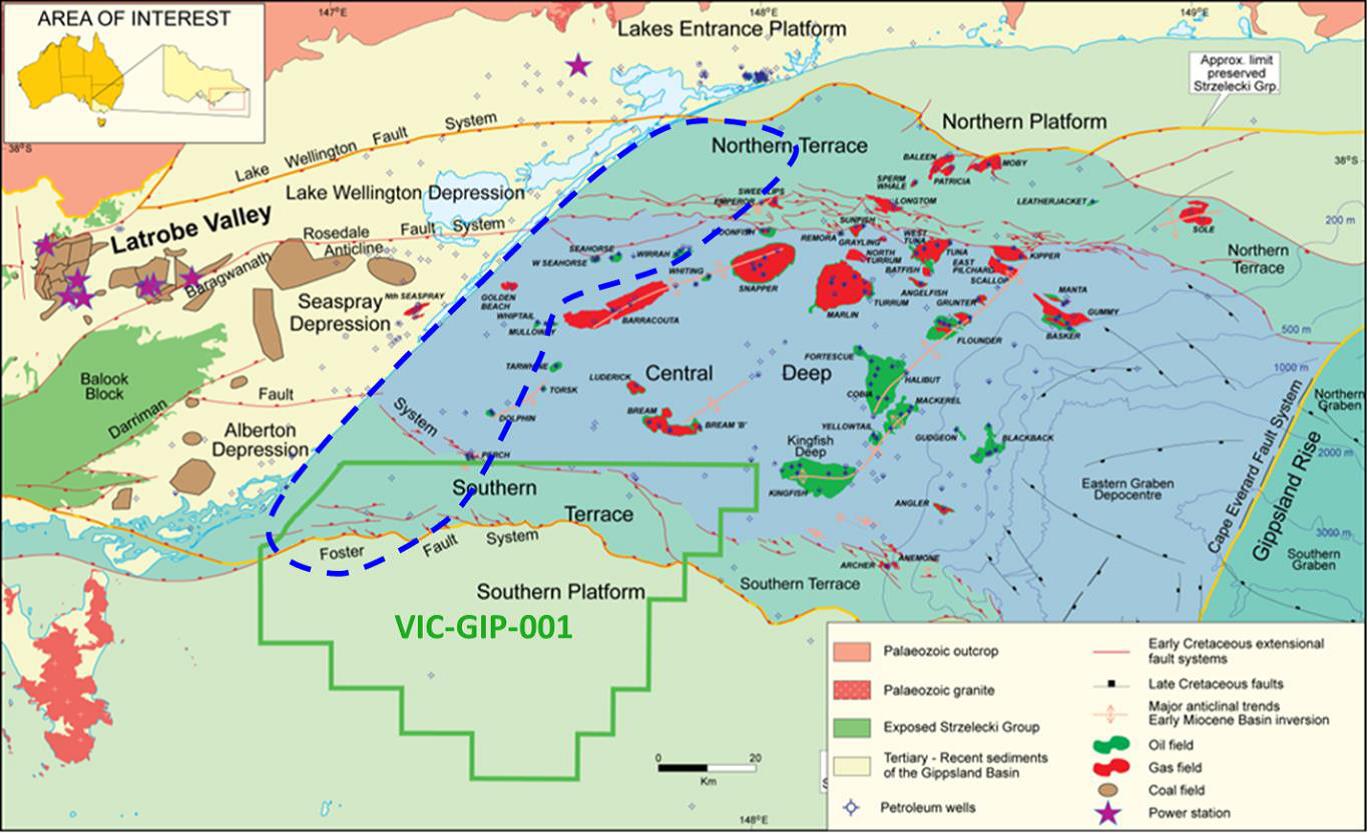
CarbonNet area of interest (blue dashed line) covers the nearshore Gippsland Basin out to approximately 25 km from the coastline
CarbonNet is one of two Australian Government Carbon Capture and Storage Flagship Program projects. The CarbonNet Project is currently in the feasibility and commercial definition stage investigating the potential for a large-scale CCS network (or 'hub') located in the Gippsland Basin, Victoria. The hub will bring together multiple CO2 capture projects, transporting the CO2 through a shared pipeline to a storage site(s) with a minimum storage capacity of 25 million tons (Mt) of CO2 and up to 125 MtCO2. CarbonNet holds the first offshore GHG permit in Australia, VIC-GIP-001 on the southern flank of the Gippsland Basin (Figure 1) which enables the Project to conduct exploration activities to search for suitable GHG storage sites.
This report, Site characterisation for carbon storage in the near shore Gippsland Basin, brings together previous studies on the Gippsland Basin with additional new analyses to undertake a site selection process to rank specific storage sites for a potential large-scale CO2 injection project for CarbonNet. The site screening process used by CarbonNet follows the DNV GL Recommended Practice DNV-RP-J203 and led to an initial set of screening requirements guiding the site selection process. 20+ sites were mapped, then screened for their fundamental suitability for CO2 storage, and ranked high or low.
After screening, three key sites were selected. They met a series of criteria including:
- nearshore location
- minimum storage capacity of >25 MtCO2
- permanent containment after 1000 years of plume modelling.
The report details the geology, storage type, and specific reservoir and seal conditions of these three sites. Importantly, for other Australian CO2 storage exploration and appraisal projects, the sites are ranked and discussed in the context of the Australian legislation. The legislation requires three fundamental storage requirements – a site must be suitable in terms of its capacity, injectivity and containment, which are addressed in this report for three key sites.
The three sites are not specifically located in the report, however descriptions of the sites are detailed. All three sites target the Latrobe Group and all have thick (from 400m up to 3 km+), high quality reservoirs and proven effective seals, including an intraformational seal in the Latrobe Group as well as the overlying Lakes Entrance Formation. The latter being the proven seal for the majority of hydrocarbon accumulations in this basin. Site one is a structural closure and underlies a small undeveloped hydrocarbon accumulation, although the CO2 reservoir is much deeper and isolated from the shallow hydrocarbons. The site is the closest to shore and would be the least cost to develop with the largest resource of more than 125 MtCO2. The second site is also a structural closure that underlies a working oilfield nearing the end of production. Once again the CO2 reservoir would be injected below the oil field with migration into the plume unlikely, albeit long after depletion of the oil. Site Two has a storage resource in excess of 50MtCO2. Finally, the third site is an open deep saline formation trap on the southern margin of the basin. In this storage scenario, the plume would travel through the reservoir under the seal southwards through a set of connected small structures. The capacity in Site Three scenario is less certain but is expected to still be larger than 25 MtCO2. Dynamic injection modelling has shown that all three storage scenarios are viable and that the required injection rates can be met.
The three key sites selected for the CarbonNet Project are high graded storage sites in the nearshore Gippsland Basin. The three potential sites progressed through the DNV screening process to obtain the DNV certification and they all met the demands of regulations in the Australian offshore storage legislation. Finally, all three met the minimum requirements of 1 Mtpa injectivity and 25 Mt storage capacity demonstrating either permanent structural trapping or cessation of the CO2 plume’s movement in an open deep saline formation. The Gippsland Basin is the premier basin in Australia for CO2 storage and is adjacent to a cluster of high-emission source points. The CarbonNet Project has had a very long history working on the Gippsland Basin and this report is an important milestone in the development of a southeastern Australia CCS hub.
|
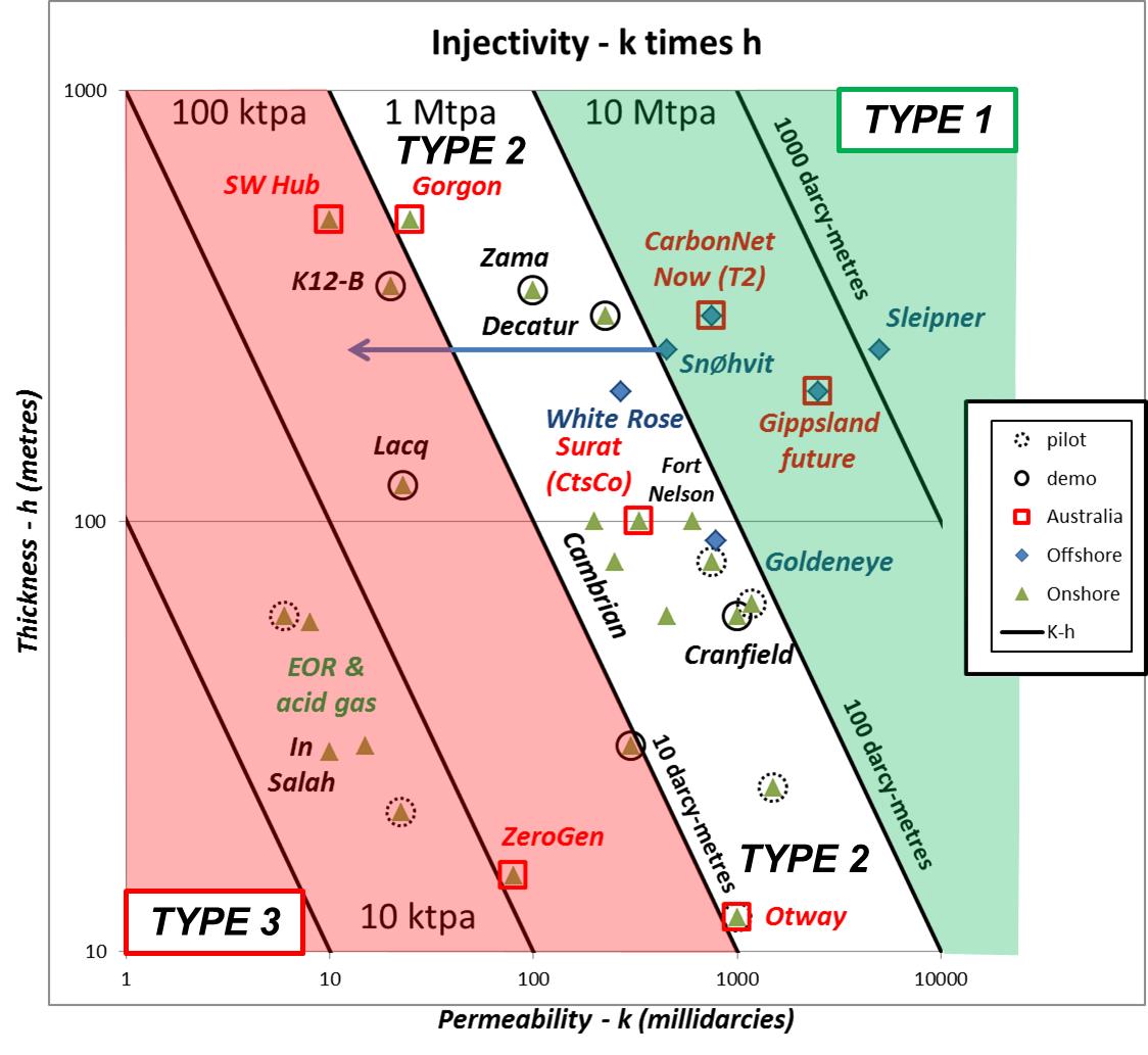
Another key output of this report is the introduction of a new classification system for storage projects based on the reservoir type. Due to its broad terminology it could be used by the CO2 storage industry to enable the quick designation of a project. Type 1: High permeability reservoirs, where injectivity per well is high. Storage capacity is determined by the physical geometry of the reservoir containing lateral plume movement and vertical containment is by an effective seal. An example is Sleipner CCS Project Type 2: Lower permeability reservoirs, where well injectivity is moderate. Capacity is determined by well number and distribution, and to a lesser extent by plume migration and sub-regional pressure constraints. Vertical containment is again by an effective seal. An example is Quest CCS Project. Type 3: Low permeability reservoirs where injectivity per well is low and total project capacity is low. Capacity will be constrained by local geomechanical stability. Vertical containment may be by an effective seal, or merely by the limited permeability of the reservoir itself. This is favoured by acid gas storage projects but would suit projects with low injection rates. An example is In Salah.
|